
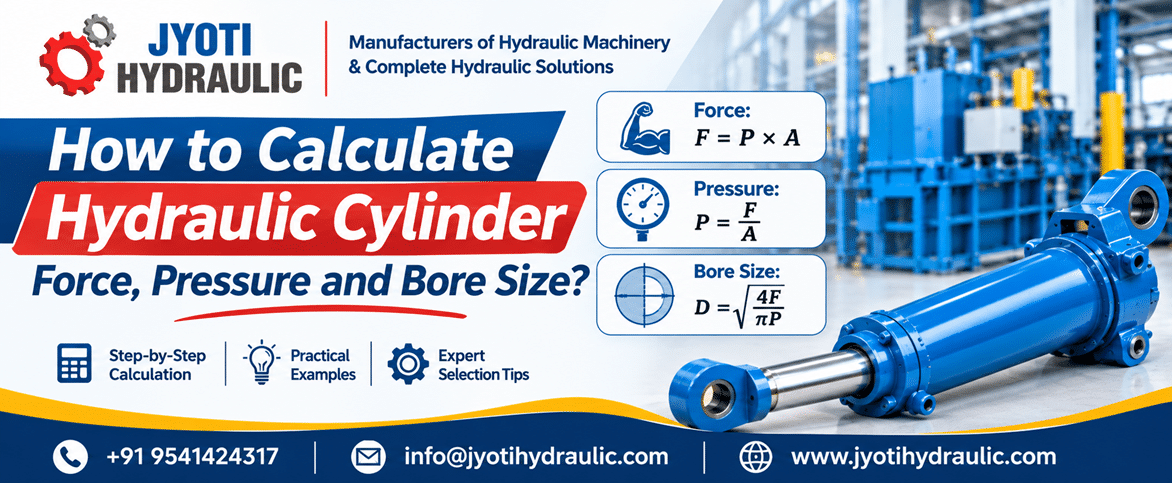
Understanding Hydraulic Cylinder Force, Pressure and Bore Size
A hydraulic cylinder converts the energy of pressurized fluid into linear mechanical movement. Fluid acts on a piston inside the cylinder barrel, producing force that is transmitted through the piston rod.
| Term | Meaning |
|---|---|
| Cylinder force | The axial pushing or pulling force, normally expressed in newtons or kilonewtons. |
| Operating pressure | The fluid pressure present at a cylinder port during a particular operating condition. |
| Bore diameter, D | The internal diameter of the cylinder barrel, used to calculate full piston area. |
| Effective piston area, A | The area exposed to pressure: full piston area on the cap side or annular area on the rod side. |
| Stroke length, S | The distance the piston and rod travel between their retracted and extended positions. |
Pressure and effective area determine theoretical hydraulic force. Stroke determines travel, while bore and stroke together determine swept oil volume. These are related selection parameters, but they are not interchangeable.
How to Calculate Hydraulic Cylinder Force
The basic formula is:
For extension using the full piston area:
Here, F is force, P is pressure, A is effective area and D is bore diameter.
Use compatible units
A convenient metric combination is:
This works because:
1 bar = 0.1 MPa
Alternatively:
Manufacturer force tables use this same pressure–area relationship.
Worked example: Extension force for an industrial press
Assume a cylinder has a 100 mm bore and 160 bar pressure at the cap-end port, with negligible rod-end pressure.
Step 1: Calculate piston area.
A = 7,853.98 mm2
Step 2: Convert pressure.
Step 3: Calculate force.
F = 125,663.71 N
F ≈ 125.66 kN
The theoretical extension force is therefore 125.66 kN.
The equations also show that doubling pressure doubles theoretical force, while doubling bore diameter quadruples piston area and theoretical force.
Why actual usable force is different
The calculated value is not automatically the force available to the machine’s working tool. Opposing chamber pressure and cylinder friction reduce available rod force. Seal design, lubrication and operating conditions affect friction, so mechanical efficiency should not be treated as a universal fixed percentage.
How to Calculate Hydraulic Cylinder Pressure
Rearranging the force equation gives:
For the same required force, a larger effective area reduces theoretical pressure demand.
Worked example: Pressure required for a clamping operation
Assume a direct-acting fixture requires 80 kN extension force from an 80 mm bore cylinder. Initially neglect friction and opposing pressure.
Step 1: Convert force.
Step 2: Calculate piston area.
A = 5,026.55 mm2
Step 3: Calculate required pressure.
P = 15.915 N/mm2
P ≈ 15.92 MPa = 159.15 bar
The ideal pressure requirement is approximately 159.15 bar at the cylinder’s cap-end port.
Pump pressure versus cylinder pressure
While oil is flowing, pressure drops occur across supply valves, pipelines, fittings and other components. Consequently, the pump outlet may need a higher pressure than the cylinder inlet. Cylinder sizing should use the pressure actually available at the relevant port, rather than assuming the pump gauge reading reaches the cylinder unchanged.
Hydraulic cylinder working pressure must also remain within the permitted limits of the selected cylinder assembly and connected components. Increasing a relief setting is not a substitute for checking those limits.
How to Calculate Hydraulic Cylinder Bore Size
For ideal full-bore extension:
Rearranging:
With force in newtons and pressure in MPa, the calculated bore is in millimetres.
Worked example: Bore required for a 100 kN load
Assume the required extension force is 100 kN and the available cap-end pressure is 160 bar.
Step 1: Convert the inputs.
P = 160 bar = 16 N/mm2
Step 2: Substitute into the formula.
Step 3: Calculate the diameter.
The result is a theoretical minimum, not a final cylinder specification. A suitable standard bore above this minimum—such as a 100 mm candidate where available—must still be checked against actual usable force, rod strength, mounting, stroke and application requirements. Manufacturer selection guidance treats bore and rod selection as connected decisions.
The design allowance should reflect peak loads, acceleration, friction, load uncertainty and applicable safety requirements. It should not be an arbitrary percentage applied to every machine.
How do bore, stroke and pump flow affect speed?
Pressure and force do not determine the required stroke. For direct linear travel:
The ideal flow relationships are:
v = Q / A
t = V / Q = S / v
Here, V is swept oil volume, Q is flow delivered to the active chamber, v is piston speed and t is travel time. Use consistent units.
For the 100 mm bore cylinder, assume a 500 mm stroke and 20 L/min constant inlet flow.
Step 1: Calculate extension oil volume.
V = 3,926,990.82 mm3
Since 1 L = 1,000,000 mm3:
Step 2: Calculate extension time.
t ≈ 11.78 s
Step 3: Calculate average travel speed under the constant-speed assumption.
v ≈ 42.44 mm/s
These ideal results exclude leakage, compression, acceleration, deceleration and cushioning. The equations show why a larger bore requires more oil for the same stroke and moves more slowly at the same inlet flow. These requirements should be considered when selecting hydraulic power pack systems.
Difference Between Hydraulic Cylinder Extension and Retraction Force
Single-rod and double-acting describe different features. Single-rod means the piston rod extends from one side of the piston. Double-acting means hydraulic pressure drives movement in both directions. A conventional cylinder can therefore be both single-rod and double-acting.
For a conventional single-rod cylinder, neglecting opposing pressure and friction:
Here, d is piston rod diameter. Retraction force is lower at the same inlet pressure because the rod occupies part of the piston area.
Worked example: Comparing push and pull force
Use a 100 mm bore, 60 mm rod and 160 bar inlet pressure for each direction.
The full piston area is:
The rod-side annular area is:
Aa = 5,026.55 mm2
Therefore:
Fretraction = 16 × 5,026.55 = 80.42 kN
Retraction force is 64% of extension force in this example.
Include both chamber pressures in a realistic calculation
When the opposite chamber is pressurized, calculate each chamber’s force separately and subtract the opposing contribution. Simply multiplying full piston area by the pressure difference is incorrect for unequal piston areas.
For extension:
For retraction:
Here, Pc and Pr are the simultaneous cap-end and rod-end gauge pressures; friction opposes the direction being considered.
For illustration, assume extension at 160 bar cap pressure, 10 bar rod-side backpressure, and 2 kN cylinder friction:
Fusable ≈ 118.64 kN
This illustrates why the initial 125.66 kN theoretical figure should not be treated as guaranteed usable output.
Important Technical Factors Affecting Hydraulic Cylinder Calculations
A complete hydraulic cylinder design review considers more than the pressure–area equation. Bore, rod size, mounting, speed, materials and operating conditions must work together.
| Factor | Effect on cylinder selection and performance |
|---|---|
| Operating pressure | Establish available pressure at the cylinder ports and check permitted operating limits, including relevant transient conditions. |
| Cylinder bore diameter | Sets full piston area. Increasing bore increases theoretical force but also increases oil demand for a given stroke. |
| Piston rod diameter | Changes retraction area and influences tensile, compressive and bending capability. A larger rod reduces available pulling area. |
| Stroke length | Must match required travel and installation geometry. Longer extension can increase unsupported length and stability concerns. |
| Required load capacity | Include process resistance, gravity where applicable, acceleration and mechanism geometry—not merely the nominal mass being moved. |
| Extension and retraction speed | Determine cycle time and cushioning needs. The two directions generally require different flow rates for equal speeds. |
| Hydraulic pump flow rate | Must supply the required chamber flow under operating conditions. Insufficient flow prevents the intended movement speed. |
| Mounting arrangement | Determines how force enters the machine. Misalignment or unsuitable mounting can introduce damaging bending loads. |
| Buckling resistance | Check compressive stability using rod size, unsupported length and end-support conditions. Adequate hydraulic force does not prove adequate buckling resistance. |
| Working environment and duty cycle | Temperature, contamination, corrosion exposure and repeated cycling affect material, seal, coating and fatigue requirements. |
| Seal friction and leakage | Friction reduces available output; leakage can affect movement and holding behaviour. Seal selection must suit pressure, fluid, speed and temperature. |
| Safety factor and mechanical limitations | Verify the barrel, rod, end connections, pins, mountings and supporting machine structure—not just piston thrust. |
Manufacturer guidance specifically addresses mounting loads, rod stability and pressure limitations, while seal-material selection depends on operating conditions.
Applications of Hydraulic Cylinder Force and Bore Calculations
Hydraulic cylinders serve industrial, mobile, material-handling and manufacturing applications. The following examples illustrate how the same calculations support different selection decisions.
| Application | Practical reason to calculate force and bore correctly |
|---|---|
| Hydraulic press machines | Match available ram force to the required forming, pressing or assembly load. |
| Hydraulic baling press machines | Evaluate compression force alongside stroke volume and the intended compaction cycle time. |
| Industrial material handling equipment | Account for payload, acceleration and mechanism leverage during transfer or positioning. |
| Hydraulic lifting systems | Evaluate lifting force at the least favourable position, not only when the mechanism is fully raised. |
| Steel and metal processing industries | Match clamping, positioning or straightening force to the actual process resistance. |
| Construction equipment | Check cylinder force throughout changing linkage positions and load conditions. |
| Agricultural machinery | Balance implement force, available hydraulic pressure, travel and movement speed. |
| Manufacturing and automation systems | Match clamping force and stroke time to the process without unnecessary oversizing. |
These are application examples, not rated capacities for particular Jyoti Hydraulic products.
Benefits of Correct Hydraulic Cylinder Sizing
Correct sizing supports dependable load handling, appropriate movement speed and better matching between the cylinder, pump and power pack. Avoiding under-sizing and unnecessary over-engineering can also improve reliability and control equipment cost.
Suitable materials, seals and alignment help avoid conditions associated with premature wear, leakage and additional maintenance. Service life still depends on installation, contamination control and operation—not dimensions alone.
A useful efficiency distinction follows directly from the equations: a larger bore can reduce required pressure, but it needs more flow to maintain the same speed. Lower pressure alone therefore does not demonstrate lower energy consumption.
How to Choose the Right Hydraulic Cylinder Manufacturer
When evaluating Hydraulic Cylinder Manufacturers, ask for evidence of relevant manufacturing experience and engineering support for your application. Discuss bore and stroke customization, pressure compatibility, mounting arrangements and the calculations supporting rod selection.
Request a specification covering piston rod material and surface finish, cylinder tube quality, seal and bearing selection, dimensional tolerances, and agreed inspection and testing requirements. These details should reflect the machine’s operating conditions rather than a generic product description.
Before choosing a hydraulic cylinder manufacturer in India, also clarify drawing approval, replacement seal availability, commissioning guidance and after-sales technical support. A useful proposal should make both the supply scope and the engineering assumptions clear.
Hydraulic Cylinder Manufacturer Price – What Factors Affect the Cost?
A meaningful Hydraulic Cylinder Manufacturer Price comparison starts with a consistent technical specification. Manufacturer quotation processes require application and configuration details because cylinders are not interchangeable solely on external dimensions.
For comparable quotations, specify the following cost-related requirements together:
Dimensions and construction: Bore diameter, stroke length, piston rod diameter and material, cylinder tube material and wall thickness, and the required operating pressure rating.
Components and configuration: Seal and bearing quality, mounting arrangement, rod-end connections and any customization such as sensing, cushioning or special coatings.
Manufacturing and verification: Required tolerances, surface-finish requirements, inspection documentation and the agreed testing scope.
Two cylinders with similar bore and stroke can consequently involve different materials, machining work, components and verification requirements. Ask suppliers to identify these differences rather than comparing only the final amount.
Request an application-specific quotation; there is no defensible universal price for every cylinder of a given bore.
Common Mistakes to Avoid During Hydraulic Cylinder Selection
Checking extension force but ignoring the rest of the load path. Selecting by bore alone overlooks operating pressure, retraction force and rod stability. A cylinder that produces sufficient theoretical pushing force may still be unsuitable for pulling or for a long compression stroke.
Choosing travel without checking movement requirements. An unsuitable stroke can prevent the required motion or create installation problems. Ignoring pump flow can leave a correctly force-sized cylinder unable to achieve the intended cycle time.
Mixing units or ignoring installation conditions. Bar, MPa and psi cannot be substituted numerically without conversion. Similarly, overlooking mounting alignment, duty cycle, temperature or fluid compatibility can undermine a sound force calculation through mechanical stress or unsuitable sealing conditions.
Future Trends in Hydraulic Cylinder Technology
Energy-efficient hydraulic systems increasingly combine hydraulic hardware with demand-based control and monitoring. Connected systems can use operating data to support diagnostics and maintenance decisions; this does not mean every cylinder includes these functions.
Improved sealing technologies include low-friction profiles and application-specific material options. Precision-manufactured sealing features seek to manage the balance between leakage control, friction and service life.
Advanced materials and surface engineering also offer opportunities for better wear and corrosion resistance. Laser-clad rod coatings and specialized corrosion-protection systems are documented examples. Customized combinations of materials, coatings, sensing and mountings should be evaluated against the application rather than assumed to be universally necessary or available.
Why Choose Jyoti Hydraulic?
Jyoti Hydraulic is an Indian hydraulic machinery and equipment manufacturer based in Faridabad. Its published product range includes hydraulic cylinders for industrial and mobile applications, with custom cylinder designs and technical support identified among its services.
The company also lists custom-engineered double acting hydraulic cylinders and application-specific hydraulic power pack systems. This provides a basis for discussing cylinder requirements together with the associated pressure and flow requirements.
For a productive enquiry, share the required push and pull forces, available pressure, bore and rod constraints, stroke, movement speed, mounting drawing and operating environment. Request confirmation of the proposed configuration against those requirements.
Conclusion
Hydraulic cylinder selection begins with three calculations:
P = F / A
D = √[4F / (πP)]
However, the calculated force or bore is only the starting point. Actual selection must account for both chamber pressures, rod diameter, stroke, flow, friction, mounting, stability and operating conditions.
Use the calculations to define a clear requirement, then consult experienced hydraulic cylinder manufacturers to verify the complete assembly and its suitability for the machine.
Frequently Asked Questions
1. How do you calculate hydraulic cylinder force?
Calculate theoretical hydraulic cylinder force using F = P × A. For extension, use A = πD2/4; for retraction, subtract the rod area. With pressure in bar and area in square millimetres, divide their product by 10,000 to obtain force in kilonewtons. Account separately for opposing pressure and friction.
2. What is the formula for hydraulic cylinder pressure?
The theoretical pressure formula is P = F/A. Divide the required force in newtons by the effective piston area in square millimetres to obtain pressure in MPa. Multiply MPa by ten for bar. Actual required inlet pressure must also overcome relevant friction and opposing chamber pressure.
3. How do you calculate hydraulic cylinder bore size?
For ideal extension, calculate bore using D = √[4F/(πP)], with force in newtons and pressure in MPa to obtain millimetres. The answer is a theoretical minimum. Final selection requires an available bore size, appropriate design allowance, and verification of rod strength, mounting and operating conditions.
4. How much force can a hydraulic cylinder produce?
Cylinder force depends on effective area and chamber pressures; it is not determined by stroke alone. In the worked example, a 100 mm bore at 160 bar produces 125.66 kN theoretical extension force. With a 60 mm rod, theoretical retraction force at the same inlet pressure is 80.42 kN.
5. Does a larger hydraulic cylinder bore increase force?
Yes, increasing bore increases theoretical extension force at the same pressure because piston area is proportional to diameter squared. A 20% increase in bore produces a 44% increase in area. However, that larger area also requires 44% more inlet flow to maintain the same ideal extension speed.
6. What is the difference between extension force and retraction force?
Extension pressure acts on the full piston area, while retraction pressure acts on the smaller annular area in a conventional single-rod cylinder. Consequently, retraction force is lower at equal inlet pressure when opposing pressure is negligible. For realistic calculations, subtract the force generated by pressure in the opposite chamber.
7. How does operating pressure affect hydraulic cylinder performance?
Higher available operating pressure increases potential force for a given effective area. However, the pressure needed during operation depends on the load, friction and opposing pressure. Pressure losses also affect what reaches the cylinder. Operation must remain within the permitted limits of the cylinder and connected hydraulic components.
8. What factors affect hydraulic cylinder manufacturer price?
Price comparisons should account for bore, stroke, pressure rating, rod and tube materials, seals, bearings, mountings, customization, tolerances and testing requirements. These specifications define the proposed supply. Obtain quotations against the same application details and drawings so that differences in scope are visible rather than hidden behind similar dimensions.
9. How do I choose the right hydraulic cylinder manufacturer?
Choose a manufacturer able to review your application and document the proposed cylinder configuration. Ask about relevant experience, design support, materials, seals, mounting options, testing and after-sales assistance. Provide load, pressure, stroke, speed and environmental requirements so the discussion goes beyond a catalogue bore size or initial price.
10. Why is piston rod diameter important in hydraulic cylinder selection?
Piston rod diameter influences compressive stability, tensile capacity and retraction force. Increasing rod diameter reduces the rod-side effective area, so it reduces theoretical pulling force at the same pressure. Rod selection must therefore balance hydraulic output with mechanical loading, unsupported length, mounting conditions and the required resistance to buckling.
Discuss Your Hydraulic Cylinder Requirements with Jyoti Hydraulic
Move from an estimated bore size to a clearly defined cylinder requirement. Contact Jyoti Hydraulic to discuss application-specific hydraulic cylinders, customized solutions, technical consultation and quotations.
Share your required force, pressure, stroke, speed and mounting details, and request guidance on suitable industrial hydraulic cylinders and associated power pack configuration.
Jyoti HydraulicEmail: info@jyotihydraulic.com
Phone: +91 9541424317
Request a customized quotation based on your actual operating requirements—not bore size alone.


