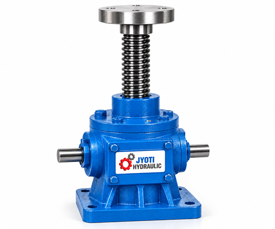
Worm Gear Screw Jack 35 Ton
Moving a heavy load is only part of the job. Bringing it to the required height, keeping it aligned and making controlled adjustments are equally important. The Worm Gear Screw Jack 35 Ton from Jyoti Hydraulic is a mechanical lifting and positioning solution for industrial applications that require substantial axial load capacity and controlled linear movement.
📞 Get in Touch
📞 +91 9541424317
📧 jyotihydraulic@gmail.com
Get Your Quote Instantly
Overview
The mechanism combines worm gear reduction with a lifting screw to convert rotary input into linear travel. It can be considered for machinery adjustment, lifting assemblies, fabrication fixtures and other engineered positioning systems. Selecting the right configuration involves more than load capacity: lifting distance, operating frequency, mounting arrangement and load guidance all affect performance.
Product overview
- Product name: Worm Gear Screw Jack 35 Ton
- Brand: Jyoti Hydraulic
- Nominal capacity designation: 35 ton, subject to the specified operating conditions
- Mechanism: Worm gear and lifting screw
- Primary function: Controlled lifting, lowering and axial positioning
- Drive arrangement: Manual or motor-driven configuration, subject to selection
- Stroke and mounting dimensions: To be specified for the application
How does a worm gear screw jack work?
The input shaft turns a worm, which engages with a worm wheel inside the gearbox. This reduction mechanism transfers motion to the screw assembly, producing linear movement.
In a translating screw arrangement, the lifting screw moves through the housing and must be restrained against rotation. In a rotating screw arrangement, the screw rotates while a suitably restrained travelling nut moves along it. The arrangement selected determines the installation space, attachment method and guidance requirements.
Movement depends on both screw lead and gear ratio. A smaller travel distance per input revolution allows finer adjustment, but requires more input revolutions to complete the same stroke. The correct balance depends on how quickly the load must move and how closely its position must be controlled.
Understanding the 35-ton capacity
The capacity designation is a starting point for selection. It should not be treated as confirmation that the jack can lift the same load at every extension, speed or operating frequency.
A load held stationary places different demands on the assembly from a load repeatedly raised and lowered. During movement, friction generates heat, and the drive must overcome the required operating torque. Starting torque also needs to be considered when choosing a motor.
For a screw loaded in compression, a longer unsupported extension can reduce permissible load because of buckling. The final selection should therefore consider the actual working load, maximum extension, end support conditions and operating cycle together.
Confirm whether the published rating refers to static capacity, dynamic capacity or both, and verify the unit basis used for “ton” in the approved specification.
Key features and practical benefits
- Controlled linear movement: Screw-driven travel supports gradual height and position adjustments.
- Worm gear reduction: Provides mechanical reduction between the input drive and lifting screw.
- Mechanical actuation: The lifting mechanism operates without a hydraulic cylinder or hydraulic power circuit.
- Drive flexibility: Manual and motorised arrangements can be evaluated according to operating torque and frequency.
- Machine integration: Stroke, mounting orientation and load connection can be selected around the equipment layout.
- Multi-point lifting potential: Compatible jacks can be incorporated into an engineered system for larger platforms or assemblies.
- Positioning flexibility: Suitable configurations can be assessed for lifting, lowering, pushing or pulling along the screw axis.
Positioning accuracy, backlash and repeatability should be specified separately. A fine movement per input revolution does not, by itself, establish the accuracy of the complete machine.
Applications for a 35-ton worm gear screw jack
This capacity class can be evaluated for industrial tasks where substantial loads need controlled movement.
Heavy equipment height adjustment: Positioning machinery sections or assemblies at a required working height, with appropriate guidance and structural support.
Fabrication and assembly fixtures: Adjusting large components during alignment, fit-up or assembly operations.
Lifting tables and platforms: Raising guided platforms where the frame, drive system and individual jack loads have been calculated together.
Process equipment adjustment: Changing the position of machine beds, support structures or production equipment during setup.
Maintenance positioning: Moving equipment into an accessible position as part of an engineered maintenance arrangement.
The jack should be selected for the actual forces in the application. Off-centre loading, vibration and shock can change the demands on the lifting assembly considerably.
Technical details to confirm before ordering
A useful specification should describe how the jack will operate, rather than list capacity alone.
| Parameter | Details to confirm |
|---|---|
| Rated load | Permissible static and dynamic axial loads |
| Stroke | Required working travel and maximum extension |
| Screw arrangement | Translating screw or rotating screw with travelling nut |
| Gear ratio | Reduction ratio suited to torque and speed requirements |
| Screw lead | Linear travel per screw revolution |
| Lifting speed | Required travel speed under the working load |
| Input torque | Starting and running torque at the selected load |
| Drive | Manual input or motor type, power and speed |
| Duty cycle | Running time, rest periods and cycles per hour |
| Mounting | Orientation, mounting dimensions and load attachment |
| Construction | Confirmed housing, screw and gear materials |
| Positioning performance | Backlash, repeatability and accuracy where required |
| Protection | Screw covers, surface protection and environmental requirements |
| Holding provisions | Back-driving assessment and any required brake or mechanical restraint |
Selecting the correct stroke and drive
Start with the minimum and maximum positions the load must reach. Include installation clearances and the space occupied by the screw in both retracted and extended positions. Specifying unnecessary stroke can increase installation size and complicate the load assessment.
Next, establish the required movement time. A jack that adjusts a machine occasionally has a different operating requirement from one that moves repeatedly throughout a production shift. Motor selection should account for load, starting torque, efficiency, speed and duty cycle.
Manual operation also requires a torque assessment. A handwheel arrangement should be selected only after checking the operating effort and number of turns needed for the intended movement.
Using multiple screw jacks together
A large platform may require several lifting points. Compatible screw jacks can be connected through shafts, couplings and gearboxes, or operated using an appropriately controlled drive arrangement.
The load should not automatically be divided equally by the number of jacks. An offset centre of gravity, a flexible platform or an unevenly placed component can increase the force at one lifting point. Each jack and transmission component must be selected for the load it may actually experience.
Platform guidance and structural stiffness are also important. Coordinated input rotation alone does not guarantee that a flexible or unevenly loaded platform will remain level.
Load holding and self-locking
Self-locking behaviour must be confirmed for the selected configuration. It depends on the screw and gearing characteristics, friction and operating conditions. The term “worm gear” alone does not establish that the load cannot drive the mechanism backwards.
Where uncontrolled movement would create a hazard, the system design should include the necessary braking or mechanical restraint. Separate support is required before maintenance beneath a raised load.
Installation and maintenance
Install the jack on a rigid, aligned mounting surface. The load should act along the intended screw axis, while external guides or supports manage lateral forces and overturning moments.
During commissioning, check travel direction, alignment, clearances and any limit controls before applying the working load. Avoid using the end of screw travel as a routine stopping method unless the assembly is specifically designed for that purpose.
Routine maintenance should include lubrication according to the supplied instructions, inspection of exposed threads, checks on couplings and fasteners, and monitoring for unusual noise, heat or increasing backlash. Protective covers may be appropriate where dust, moisture or process debris could reach the screw.
Frequently asked questions
Can this jack lift 35 tons through its full stroke?
This must be confirmed for the selected configuration. Permissible load can depend on extension, screw support, speed and duty cycle.
Can the jack operate horizontally?
Horizontal operation may be possible with a suitable configuration. The load must be independently supported and guided, and the mounting and lubrication requirements must be checked.
Is the jack suitable for continuous operation?
Continuous-duty suitability should not be assumed. Frictional heat and the selected operating conditions determine the permissible duty cycle.
Can several jacks lift one platform?
Yes, a compatible multi-jack system can be engineered for this purpose. Load distribution, drive coordination, platform stiffness and guidance all require assessment.
What determines the price?
Price depends on stroke, screw arrangement, drive, mounting requirements, materials, protective accessories and the scope of supply. A complete application specification allows a more accurate quotation.
Discuss your requirement with Jyoti Hydraulic
For a Worm Gear Screw Jack 35 Ton, share the working load, required stroke, lifting speed, operating frequency and installation drawing with Jyoti Hydraulic. These details help define a configuration suited to your equipment and provide a clear basis for the technical offer and quotation.
Blogs
-
Hydraulic Cylinder with Power Pack Manufacturers in India – Jyoti Hydraulic
Read MoreJyoti Hydraulic brings the conversation about hydraulic cylinders and power…
-
PET Bottle Hydraulic Baling Press Machine: Working, Benefits & Applications – Jyoti Hydraulic
Read MoreJyoti Hydraulic offers PET bottle baling equipment for businesses that…
-
Hydraulic Jack Price in India – Latest 2026 Guide | Jyoti Hydraulic
Read MoreJyoti Hydraulic offers industrial hydraulic lifting solutions designed for strength,…