
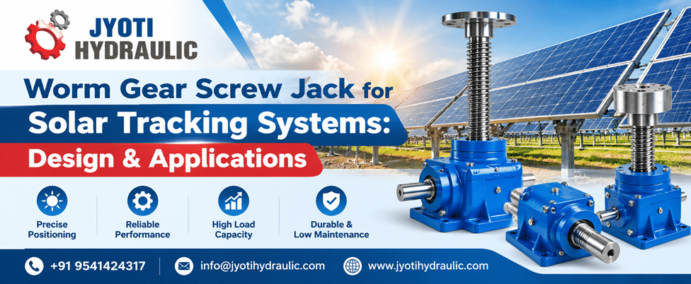
Jyoti Hydraulic puts the focus on a critical question in solar tracking: how do you move a large panel assembly accurately, then keep it stable when operating conditions change? The answer involves more than selecting a motor. Tracker performance depends on the relationship between actuator force, mounting geometry, structural stiffness, environmental protection and control logic. A correctly specified Worm Gear Screw Jack can provide the controlled linear movement needed to adjust panel orientation while supporting a practical maintenance strategy.
For solar developers, equipment manufacturers and engineering procurement teams, understanding these details helps prevent expensive mistakes. An actuator may move a tracker successfully during a workshop trial yet struggle outdoors because wind loading, screw extension or mounting misalignment was overlooked.
This guide explains how worm gear screw jacks work in solar tracking systems, where they fit, and what to evaluate before selecting one.
What Is a Worm Gear Screw Jack in a Solar Tracking System?
A worm gear screw jack is a mechanical actuator that converts rotary input into linear movement through a worm gear reduction and screw mechanism. In a solar tracker, that movement acts through a bracket or linkage to change the panel assembly’s angle.
The jack provides mechanical motion; the tracker controller determines when and how far to move.
A typical installation includes:
- An electric motor and drive arrangement.
- A worm shaft, worm wheel and load-carrying screw.
- Bearings, housing, seals and lubrication.
- Mounting joints connecting the actuator to the supporting structure.
- Travel limits and, where required, position feedback.
The operating principle is straightforward. Reliable performance comes from matching the complete assembly to the tracker’s loads and movement requirements.
Industry Overview: Where Screw Jacks Fit in Solar Tracking
Solar trackers adjust module orientation as the sun moves across the sky. Their value depends on site conditions, system design, shading, operating availability and the cost of the tracking equipment.
Different tracker architectures use different drive systems. Slew drives, geared rotary drives and linear actuators each have suitable applications. A screw jack is particularly relevant when the mechanism needs a controlled push or pull between two mounting points.
Commercial solar-specific screw jack designs are available in both machine screw and ball screw configurations, demonstrating that actuator selection can be tailored to load, speed and travel requirements.
The essential engineering distinction is between moving the tracker during normal operation and withstanding loads while stationary. Those duties can impose very different demands. A low daily operating time does not automatically mean an easy mechanical application.
Technical Insights: Designing the Actuator Around the Tracker
1. Calculate Force From Tracker Geometry
Panel mass alone does not determine the required actuator force. Engineers must evaluate the moments acting about the tracker’s pivot and the actuator’s effective lever arm.
A simplified relationship is:
Actuator force = required pivot moment ÷ perpendicular lever arm
For example, assume a tracker requires a resisting moment of 3,000 N·m at a particular position. With a perpendicular lever arm of 0.30 m, the ideal actuator force is:
3,000 ÷ 0.30 = 10,000 N, or 10 kN
If the lever arm decreases to 0.15 m elsewhere in the travel, the same moment requires 20 kN.
This illustrative calculation excludes friction, dynamic effects and design factors. Its purpose is to show why actuator force must be checked across the full angular range. A mounting arrangement that works near the centre of travel can demand much greater force near an endpoint.
The load assessment should include panel and frame weight, wind effects, applicable snow loading, bearing resistance and acceleration or stopping loads.
2. Select Stroke From the Actual Linkage
Stroke is the difference between the required actuator lengths at the two travel extremes. It should be calculated from the mounting coordinates and tracker rotation, rather than estimated from the desired panel angle alone.
Check:
- Closed and extended mounting lengths.
- Clearance throughout the sweep.
- Joint articulation at both ends.
- Access for lubrication and inspection.
- Required travel to the designated stow position.
For a translating screw arrangement, the design must also prevent unwanted screw rotation. Depending on the configuration, this may be achieved by the attached structure or a dedicated anti-rotation feature.
3. Check Compression Buckling
A long, extended screw under compression can buckle before reaching the jack’s nominal axial load rating. Selection therefore needs to account for unsupported length, screw dimensions and end restraint.
Manufacturer guidance explicitly treats column strength as a separate selection check for compressive applications. A housing capacity alone is insufficient to establish the allowable load at maximum extension.
This matters particularly when a tracker uses a long stroke or changes between tensile and compressive loading as its orientation and wind conditions change.
4. Keep Side Loads Out of the Screw
The screw should primarily carry axial force. Misaligned brackets, restricted pivots or frame distortion can introduce bending loads that increase friction and accelerate wear.
Use suitable pivoting mounts and adequate structural guidance so the actuator can follow the changing linkage angle. Manufacturer guidance recommends transferring side loads into guides rather than relying on the jack to resist them.
During commissioning, inspect alignment across the entire travel. Smooth operation at one position does not prove that the mounting geometry is correct everywhere.
5. Balance Gear Ratio, Screw Lead and Speed
Gear ratio and screw lead determine linear travel per input revolution.
For a conventional arrangement:
Linear speed = input rotational speed × screw lead ÷ gear reduction ratio
With a 1,200 rpm input, a 6 mm screw lead and a 24:1 reduction, the theoretical linear speed is 300 mm/min.
This is a kinematic example, not a product specification. Actual selection also depends on permitted input speed, starting torque, efficiency and thermal limits.
Normal solar tracking may require only small movements. Emergency stowing can require a longer movement within a defined time. Both duties must be checked.
Conventional worm gear screw jacks commonly have intermittent-duty limits at rated load because mechanical losses generate heat. The selected unit’s allowable duty cycle must therefore be verified for the actual load and operating conditions.
6. Verify Load Holding and Backdriving
A worm gear screw jack is not automatically self-locking.
Load-holding behaviour depends on the screw and gearing configuration, friction and operating conditions. Some arrangements require a brake or another holding device; manufacturer documentation, for example, identifies certain double-start screw configurations as non-self-locking.
For a solar tracker, establish the required behaviour during power loss and fluctuating wind loads. Ask for confirmation for the exact proposed configuration rather than accepting a general statement about worm gears.
7. Account for Backlash and Structural Deflection
Backlash creates lost motion when the drive changes direction. However, screw and gear clearances are only part of the positioning error.
Clevis-pin clearance, bracket flexibility, bearing movement and torque-tube twist can also affect the panel angle. A precise actuator cannot compensate for an excessively flexible mounting structure.
Where angular accuracy matters, evaluate the complete mechanical chain. Direct angle feedback may provide more useful information than motor rotation alone.
Applications of Worm Gear Screw Jacks in Solar Systems
Single-Axis Tracker Linkages
A screw jack can drive a lever connected to a panel table or torque tube. This arrangement suits architectures where linear actuator travel can deliver the required rotation without excessive force or interference.
Dual-Axis Elevation Adjustment
In a dual-axis system, a screw jack can control elevation while a separate mechanism controls azimuth. The elevation actuator must accommodate changing geometry and load direction throughout its operating envelope.
Seasonal Tilt Adjustment
Some installations require occasional tilt changes rather than daily tracking. A manual or motorised screw jack can make those adjustments more controlled and repeatable, provided the structure and locking arrangement are designed accordingly.
Test Rigs and Specialist Solar Equipment
Prototype trackers, research platforms and module positioning fixtures may benefit from accessible mechanical adjustment. Concentrating solar applications can also use linear positioning mechanisms, but their pointing requirements demand a separate accuracy assessment.
Benefits of a Properly Selected Screw Jack
The main benefits arise from matching the mechanism to the application:
| Benefit | Practical value |
|---|---|
| Controlled linear travel | Enables predictable movement through a designed linkage |
| Mechanical reduction | Matches motor rotation to slower actuator movement |
| Configuration flexibility | Allows engineers to select suitable stroke, mounting and drive arrangements |
| Potential load holding | Can reduce holding-power needs where the exact configuration is verified |
| Serviceable construction | Supports planned inspection of lubrication, joints and protective components |
These benefits involve trade-offs. Higher reduction can reduce movement speed, while friction affects efficiency and heating. Evaluate the complete operating cycle rather than choosing on load rating or purchase price alone.
Buying Guide: How to Compare Worm Gear Screw Jack Manufacturers
When comparing Worm Gear Screw Jack Manufacturers, request an application-based proposal supported by calculations and drawings.
A useful enquiry should include:
| Selection input | What the supplier needs to assess |
|---|---|
| Maximum tension and compression | Moving and stationary loads in both directions |
| Tracker mounting geometry | Force variation across the angular range |
| Stroke and mounting lengths | Travel, clearance and installation fit |
| Maximum unsupported screw length | Compression buckling |
| Tracking and stowing speeds | Gear ratio, input speed and motor requirements |
| Operating cycle | Starts, running time, dwell periods and thermal duty |
| Site environment | Temperature, dust, moisture and corrosion exposure |
| Positioning requirement | Backlash, feedback and repeatability |
| Power-loss behaviour | Brake, holding and backup-power requirements |
Ask suppliers to distinguish static capacity, dynamic capacity and permissible compression at the specified extension.
Also request installation instructions, lubrication requirements, spare-part availability and a general arrangement drawing. For Jyoti Hydraulic, sharing these details with your enquiry provides a clearer starting point for discussing a suitable configuration and quotation.
Installation and Maintenance in Outdoor Conditions
Outdoor reliability depends on protecting the screw and maintaining alignment.
Specify coatings, seals, bellows or protective tubes according to the site environment. Coastal exposure, airborne dust and large temperature swings create different demands.
A practical maintenance plan should cover lubricant condition, screw protection, mounting fasteners, pivot wear, travel-limit operation and corrosion. Trending motor current under comparable operating conditions can help identify increasing resistance, although current alone does not establish the cause.
Inspect the tracker after installation settlement or structural repairs. Changes in alignment can increase actuator loading even when the motor and jack remain unchanged.
Future Design Priorities: Feedback and Coordinated Stowing
Position feedback offers a useful route to better diagnostics. Solar actuator and screw jack configurations can incorporate devices such as encoders, resolvers or potentiometers, depending on the product and control requirements.
Another priority is coordination between weather sensing, controls and mechanical movement. Wind stow strategies move trackers to a designated protective orientation ahead of high-wind conditions.
For designers, the practical implication is to assess detection, command delays, available power and travel time together. The actuator’s ability to hold a stationary load does not establish whether the system can reach its stow position quickly enough.
Conclusion
A Worm Gear Screw Jack can be an effective positioning component for solar tracking when force, stroke, mounting geometry and operating duty are evaluated together.
The strongest designs account for changing leverage, compression buckling, side loads, backlash and outdoor exposure from the beginning. They also treat normal tracking, emergency stowing and stationary load holding as distinct operating requirements.
For buyers, a detailed application enquiry makes supplier recommendations easier to compare and reduces the risk of selecting a component that fits the drawing but struggles in service.
Frequently Asked Questions
What does a worm gear screw jack do in a solar tracker?
It converts rotary input into linear movement. Through a linkage, that movement changes the panel assembly’s angle in response to the tracker controller.
Are all worm gear screw jacks self-locking?
No. Self-locking depends on the specific screw and gearing arrangement and operating conditions. Obtain confirmation for the selected configuration and assess whether a brake or separate holding device is required.
How do I calculate the required actuator capacity?
Determine the tracker’s resisting moment and divide it by the actuator’s perpendicular lever arm at each relevant position. Then account for applicable load combinations, friction, dynamic effects and design factors.
Can one screw jack operate multiple panels?
Yes, where the supporting structure and transmission are designed for the combined load. Check torque distribution, structural twist, alignment and the consequences of uneven loading.
How much stroke does a solar tracker need?
Stroke depends on the mounting coordinates and required angular travel. Calculate the actuator length across the complete movement range, including the stow position.
Does a screw jack improve solar energy output by itself?
No. It enables positioning. Any energy benefit depends on the complete tracking system, site conditions, shading, control strategy and operating availability.
What should I send when requesting a quotation?
Provide drawings, tension and compression loads, stroke, mounting dimensions, speed, duty cycle, supply voltage, environmental conditions and the required power-loss behaviour.
Discuss Your Solar Tracking Requirement With Jyoti Hydraulic
Planning a new tracker or reviewing an existing actuator arrangement? Contact Jyoti Hydraulic to request a quotation and expert consultation for your worm gear screw jack requirement.
Share your tracker drawings and operating details to discuss load capacity, stroke, mounting and drive selection for your project.
📧 Email: info@jyotihydraulic.com
📞 Call: +91 9541424317


