
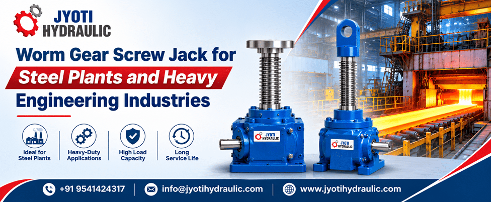
Jyoti Hydraulic manufactures worm gear screw jacks for industrial lifting and positioning applications. For steel plants and heavy engineering workshops, choosing this equipment involves more than matching a load to a catalogue rating. The real question is whether the complete lifting arrangement can move, position and support the actual load throughout its required stroke and operating cycle. That is where careful specification becomes more valuable than simply selecting a larger jack.
Consider an adjustable production table: the equipment must reach the required height, remain aligned and accommodate the way material is distributed across its surface. A useful purchasing discussion therefore starts with the application—not the model number.
This guide examines the operating principles, practical applications and selection decisions that matter when specifying screw-jack systems for demanding industrial environments.
Industry Overview: Where Steel Plants Need Controlled Linear Motion
Steel production requires many movements beyond the main rolling process. Plate levellers need positioning, straightening equipment requires roller adjustments, and pipe-processing lines use adjustable tables and centring stops. Screw-jack systems have established applications in these areas, including coordinated arrangements that move several support points together.
The operating environment must also be part of the specification. A jack installed near a hot process, exposed to contamination or subjected to vibration needs a different assessment from one operating in a clean assembly area. Manufacturers’ application-selection forms therefore consider temperature, environmental conditions, mounting orientation and load guidance alongside capacity and stroke.
For buyers, the implication is straightforward: “suitable for heavy industry” is not a complete technical specification. The supplier needs to understand what the equipment will actually experience.
What Is a Worm Gear Screw Jack?
A Worm Gear Screw Jack is a mechanical actuator that converts rotary input into controlled linear movement. A manually operated shaft or motor drives a worm, which turns a worm wheel. The screw-and-nut arrangement then produces the movement needed to lift, lower, push, pull or position a load. In a translating design, the lifting screw must be restrained against rotation so that it moves through the jack body.
Two common configurations suit different machine layouts:
Translating screw: The screw extends and retracts through the housing. Its rotation is restrained by the connected structure or an appropriate anti-rotation arrangement.
Rotating screw with travelling nut: The screw rotates without moving axially, while a nut attached to the load travels along it. This arrangement can suit installations where clearance beneath the jack is restricted.
Importantly, worm gear describes the drive arrangement, while machine screw and ball screw describe the screw mechanism. A worm-geared jack can use either screw type; the terms are not interchangeable categories.
Technical Insights: What Determines Real Operating Performance?
Load Capacity Must Be Checked at the Required Extension
A jack’s stated capacity does not automatically establish its suitability at every stroke length. When the screw carries a compressive load, its extended length becomes important because the screw must resist buckling as a column.
Long-stroke applications therefore require a check of screw diameter, unsupported length, loading direction and support arrangement. A unit that is satisfactory at a short extension may need a different screw or configuration at a greater extension.
The selection question should be: “What load can this configuration carry at my maximum working extension?”
Side Loads Need a Separate Load Path
Screw jacks primarily handle axial force. They should not be treated as substitutes for guide rails or structural supports that resist lateral forces and overturning moments.
For an adjustable table, suitable guides should carry the side loads while the jacks provide the lifting force. Misalignment and lateral loading can increase operating torque and shorten component life, particularly when the screw is extended.
This distinction matters when material enters a machine from the side or when a workpiece’s centre of gravity moves during processing.
Gear Ratio and Screw Lead Determine Theoretical Travel Speed
The basic relationship is:
Linear speed = jack input speed × screw lead ÷ worm reduction ratio
For an illustrative arrangement with a jack input speed of 900 revolutions per minute, a screw lead of 6 millimetres per revolution and a 24:1 reduction ratio:
Linear speed = 900 × 6 ÷ 24 = 225 millimetres per minute
This is a movement calculation, not confirmation that the jack may operate at that speed. The proposed operating point must still satisfy the manufacturer’s load, input-speed and duty limitations.
Use the speed at the jack input shaft in the calculation—not necessarily the motor speed, because an additional gearbox may sit between them.
Duty Cycle Is a Thermal Question, Not Just a Scheduling Detail
Sliding contact between a machine screw and its nut generates heat. Consequently, the number of movements, their duration and the rest periods between them all affect suitability.
A jack that makes occasional adjustments is performing a different duty from one that repeatedly traverses its full stroke. Machine-screw designs generally require time for heat dissipation; higher-duty applications may justify evaluating ball-screw or other actuator arrangements.
A plant running continuously does not necessarily require every actuator to run continuously. Specify the jack’s actual movement sequence.
Self-Locking Is Conditional—Not a Complete Safety System
Some machine-screw configurations resist back-driving and can hold position without continuous drive power. However, self-locking must be confirmed for the selected design. Ball-screw arrangements and certain higher-lead machine-screw configurations require braking, and vibration can create additional holding requirements.
Never interpret “worm geared” as an automatic guarantee against unintended movement. The holding arrangement must be assessed for the application.
Backlash Must Be Considered Separately from Positioning Accuracy
Backlash is clearance within the transmission. In machine-screw jacks, some clearance is necessary for operation, but it becomes particularly relevant when the axial load changes between compression and tension.
An anti-backlash mechanism can reduce axial play in an appropriate machine-screw design. Ball-screw arrangements may instead use a preloaded nut. Neither feature should be assumed to be standard.
For procurement, state the acceptable movement or positioning tolerance rather than asking only for “high precision.”
Multi-Jack Movement Requires a Coordinated System
Several jacks can be linked through shafts, couplings and bevel gearboxes so that one motor drives them together. Alternatively, individually motorised jacks can operate through an electronic control system with suitable position feedback.
Starting several independent motors simultaneously is not equivalent to providing controlled synchronisation. The drive arrangement and feedback strategy must be designed as a system.
Applications in Steel Plants and Heavy Engineering
The following applications illustrate where controlled screw-driven movement can be useful. Final suitability depends on the forces, movement profile and machine design.
| Application | Function of the Screw-Jack Arrangement | Important Selection Consideration |
|---|---|---|
| Plate levelling equipment | Positions the levelling assembly | Load, guidance and adjustment requirements |
| Section straighteners | Adjusts straightening or pinch-roller positions | Process forces and coordinated movement |
| Cooling and processing tables | Provides controlled adjustment of supporting structures | Load distribution and operating sequence |
| Pipe and hollow-section lines | Positions adjustable tables and centring stops | Required travel and repeatable settings |
These application types are documented in industrial screw-jack installations; they should not be interpreted as confirmation that any standard jack suits every machine in those categories.
Heavy engineering also includes application-specific maintenance systems. For example, purpose-designed electromechanical jacking arrangements have been used for changing steel-industry zinc baths. Such installations illustrate the importance of engineering the complete lifting system rather than treating a group of jacks as unrelated components.
Benefits of a Correctly Engineered Screw-Jack System
Controlled Adjustment of Substantial Loads
Screw jacks provide an established method of lifting and positioning industrial loads. Their practical value is especially clear when the task requires deliberate adjustment rather than rapid travel. The selected load, speed and duty must still remain within the unit’s operating limits.
Coordinated Movement Across Several Support Points
Mechanical linking allows multiple lifting points to move together from a common drive. Electronic synchronisation offers another approach where independently driven axes are more suitable. Both arrangements can support equipment layouts that need more than one lifting point.
An Alternative to a Hydraulic Circuit for Selected Movements
An electromechanical arrangement can remove the need for a hydraulic actuation circuit for that particular movement. However, screw jacks still require lubrication and maintenance. Replacing hydraulic actuation should therefore be evaluated against the application’s requirements—not presented as an automatic improvement in every case.
Buying Guide: How to Compare Worm Gear Screw Jack Manufacturers
The strongest quotation is not necessarily the one with the highest stated capacity or the lowest initial price. It is the quotation that clearly connects the proposed equipment to your operating conditions.
Prepare an Application Brief Before Requesting Prices
Start with the following information:
| Selection Input | Information to Provide |
|---|---|
| Load | Maximum working and stationary load at each lifting point |
| Movement | Required stroke, travel speed and mounting orientation |
| Operating sequence | Extension time, holding time, retraction time and cycles per hour |
| Accuracy | Acceptable positioning error and axial play |
| Environment | Temperature range, contamination, moisture and vibration |
| Layout | Number of jacks, spacing, guidance, mounting interfaces and drive arrangement |
These categories reflect the information manufacturers use to assess screw-jack applications. Include a layout sketch so that the supplier can understand the load path and installation constraints.
Do Not Size a Multi-Jack System Using Average Load Alone
Consider an illustrative example, not a product recommendation.
A table and its payload have a combined mass of 12,000 kilograms. Using gravitational acceleration of 9.81 metres per second squared:
Total gravitational force = 12,000 × 9.81 = 117,720 newtons, or approximately 117.7 kilonewtons.
With four perfectly equally loaded supports, the average would be:
117.7 ÷ 4 = approximately 29.4 kilonewtons per jack.
That calculation establishes only the ideal average. It does not establish the required jack rating. The engineering assessment must determine how the load is actually shared and include relevant operating forces and design margins.
Ask the supplier to explain the basis for the most heavily loaded jack, rather than simply dividing the total mass by the number of units.
Request Evidence Behind the Proposed Selection
When comparing Worm Gear Screw Jack Manufacturers, ask for the approved dimensional drawing, identified operating limits, selection calculations where applicable, installation instructions and maintenance requirements.
The review should address static and moving loads, extension, input speed and duty—not capacity alone. Manufacturers’ safety guidance specifically requires these parameters to be verified before operation.
Also clarify the commercial scope. Does the quotation include only the jacks, or also the motor, gearbox, shafts, couplings, guards, sensors and controls? Record exclusions explicitly so that competing offers can be compared fairly.
Discuss Maintenance Access Before Approving the Layout
Useful questions include: Can the lubrication points be reached? Can inspection take place without dismantling neighbouring equipment? What space is needed to remove the screw or replace a wear component? Which spare parts should be held on site?
These questions turn maintenance from an afterthought into part of the purchasing decision.
Installation and Maintenance: Protecting the Selected Equipment
Correct selection must be followed by correct installation. Mount the jacks on structures suitable for the operating loads, and ensure the mounting arrangement does not impose unintended misalignment. Installation and inspection should be handled by qualified personnel, using the instructions for the supplied equipment.
Provide appropriate travel-limit controls. A mechanical stop should not be used as the normal method of stopping a powered jack; driving into a hard stop can damage the mechanism.
Protective boots and screw covers can help shield exposed components from debris, but their suitability and installation space must be considered during selection.
Follow the specified lubrication and inspection schedule. Before servicing, secure or remove the load and follow the equipment’s isolation procedure. A stationary load should never be assumed safe merely because the drive has stopped.
Future Trends: Better Feedback and More Useful Operating Data
A practical direction for future upgrades is to make screw-jack systems easier to monitor. Encoders can provide speed and position feedback, while suitable limit switches can identify travel boundaries. These components are already available for integration into industrial jacking arrangements.
Load cells, load pins and associated data-logging systems can also provide information about operating loads. For a plant planning an upgrade, it is worth asking which measurements would help operators verify the process or help maintenance teams investigate a developing problem.
The objective should be useful information, not instrumentation for its own sake. Define what an abnormal reading means, who responds to it and whether the control system must stop movement. Monitoring should support—not replace—the underlying mechanical design.
Conclusion
A successful screw-jack installation begins with a clear understanding of the job: the load, the movement, the environment and the consequences of an interruption or failure.
For steel plants and heavy engineering industries, the most useful purchasing approach is to assess the complete system rather than focus on nominal tonnage. A properly documented specification gives the buyer and manufacturer a shared basis for selecting equipment, reviewing installation details and planning maintenance.
Bring that application information to Jyoti Hydraulic before finalising the model. The right discussion starts with what your machine must do.
Frequently Asked Questions
What is a worm gear screw jack used for in a steel plant?
It is used for controlled lifting and positioning tasks such as table adjustment, leveller positioning and centring-stop movement. The correct configuration depends on the process forces, stroke and operating sequence.
Are all worm gear screw jacks self-locking?
No. Holding behaviour depends on the screw and transmission configuration. Some machine-screw designs are self-locking, while other designs require a brake or external locking arrangement. Confirm this for the specific unit and application.
Can a screw jack operate continuously?
Continuous operation must be explicitly supported by the selected design and operating conditions. A higher-duty application may require a ball-screw or roller-screw arrangement rather than a conventional machine-screw design.
Can several screw jacks lift one structure together?
Yes. Multiple units can be mechanically linked to a common drive or electronically synchronised using suitable feedback. The arrangement must be engineered for the structure and its load distribution.
Does a longer stroke affect load capacity?
It can. Greater extension can make column strength a limiting factor when the screw is in compression. Check the permissible load for the actual screw length and support arrangement, not only the jack’s headline capacity.
Is a ball screw jack the same as a worm gear screw jack?
Not necessarily. “Ball screw” identifies the screw mechanism; “worm gear” identifies the drive arrangement. A ball-screw jack can incorporate worm gearing, so buyers should specify both aspects of the required design.
What should buyers ask worm gear screw jack manufacturers?
Ask how the proposed model meets the required load, stroke, speed, duty and environmental conditions. Also request installation documentation, maintenance requirements and a clear statement of what the quotation includes.
Discuss Your Application with Jyoti Hydraulic
Specify your next lifting or positioning system with a clear understanding of the job it must perform.
Contact Jyoti Hydraulic to discuss your steel-plant or heavy-engineering application, request a quotation and get expert consultation on your requirements. Share the load, stroke, movement speed, operating cycle and layout drawing to make the discussion specific to your equipment.
📧 info@jyotihydraulic.com
📞 +91 9541424317
Start with your application requirements—contact Jyoti Hydraulic today.


